Review — Han VCIP’20: HDR Image Compression with Convolutional Autoencoder (HDR JPEG Image Compression)

In this paper, HDR Image Compression with Convolutional Autoencoder, (Han VCIP’20), is briefly reviewed. In this paper:
- A two-layer High Dynamic Range (HDR) image compression framework based on convolutional neural networks is proposed.
- At the base layer, it is a JPEG codec, for backward compatibility.
- At the extension/enhancement layer, it is an autoencoder.
This is a paper in 2020 VCIP. (Sik-Ho Tsang @ Medium)
Outline
- Proposed Two-Layer HDR Image Compression Framework
- Proposed Autoencoder & Post-Processing Networks
- Experimental Results
1. Proposed Two-Layer HDR Image Compression Framework
1.1. Encoder Framework

- The original HDR image is tone-mapped (Tone-Mapping Operation, TMO) to obtain the Low Dynamic Range (LDR) image, and encoded by JPEG encoder.
- The encoded image is decoded again and performed with the inverse tone-mapping operation (ITMO).
- Finally, the residual value is the difference between the original HDR image and the new HDR image. The residual value is normalized and mapped between 0 and 255:

- At the extension layer, a CNN autoencoder is used to encode the residual image.
- Then binary quantization and arithmetic coding are performed to generate the extension layer codestream.
1.2. Decoder Framework

- First, the base layer codestream is decoded by JPEG decoder and obtained the LDR image.
- The reconstructed LDR image passes through ITMO and then generates a new HDR image.
- Then, the extension layer codestream is decoded by the decoder in the CNN autoencoder. After that the inverse residual mapping (RM) is used to generate the reconstruction residual.
- Finally, the reconstructed residual and the new HDR image are added together to form HDR image, and then passed through the post-processing module based on a group convolutional neural networks.
2. Proposed Autoencoder & Post-Processing Networks

- Residual decoder and encoder are composed of convolution, deconvolution and GDN/IGDN.
- GDN/IGDN is used because it has proved to be particularly suitable for evaluating image quality for image compression.
2.1. Residual Encoder & Decoder
- In the residual encoder, a feature fusion structure to concatenate and fuse features of different convolutional layers.
- The original residual image is down-sampled to 1/2, 1/4, 1/8, 1/16 by the convolutional layer. Then the down-sampled features is applied with a 1×1 convolution to generate the encoded representation y.
- In the end of encoder, the original residual image (H×W×3) is down-sampled to a feature map of H/16×W/16×32 size.
- In the residual decoder, the coded stream ^y is upsampled to a reconstruction residual image of H×W×3 size.
2.2. Binarizer
- It is used to control and reduce the length of coded stream.
- The binarization process consists of two parts.
- In the first step, the sigmoid activation function is used after the last 1×1 convolutional layer of the residual encoder, the residual encoder output y = E(x) should be in the range of [0, 1].
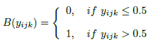
- For the second part, let yijk denote the elements in y. The binarizer B(E(x)) is defined as follows:
- But the above equation is not good for back-propagation.
- A generalization function ~B(yijk) is designed to approximate B(yijk) function as follows:
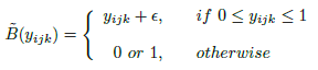
- where ε is random noise.
The B(yijk) function is only used in forward propagation calculation, while ~B(yijk) is used in back propagation.
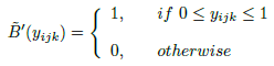
- The gradient of ~B(yijk) function can be obtained by:
2.3. Residual Reconstruction And Rate Control
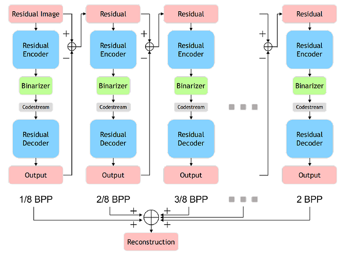
An iterative accumulation way to control the extension layer bit rate and reconstruct the original residual image.
- In the first iteration, the input image of the encoder is the original residual image.
- In each subsequent iteration, the input image is the residual, the output image is the prediction of the residual, and the residual here refers to the difference between the input image and the output image of the previous iteration.
- The final residual image reconstruction is then the sum of the output images in all iterations.
- (This part is used in some prior arts. The concept is similar to quality/SNR scalability in scalable coding)
2.4. Post-Processing
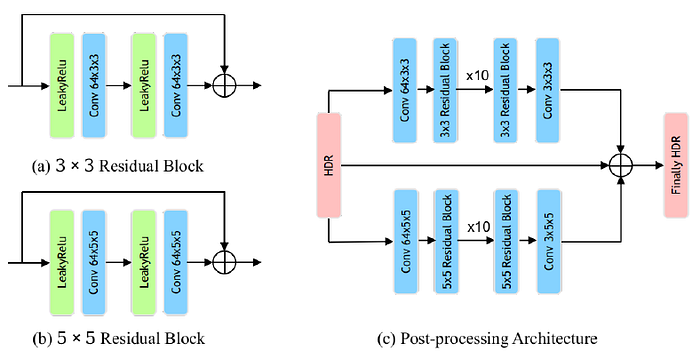
- The post-processing module is a two-layer group convolutional neural networks. The network is mainly composed of 3×3 and 5×5 residual blocks.
- 10 residual blocks are used in each group of neural networks, so as to further improve the quality of image reconstruction.
3. Experimental Results
3.1. Training Set
- The original HDR image comes from the public Internet HDR image dataset and video sequence[15] (including HDReye, Fairchild, Funt, MPI, etc.).
- These HDR images are decomposed into non-overlapping 256×256 image blocks.
- With flipping, rotating and setting different quality q in the traditional JPEG codec. In the end, about 0.35 million residual image blocks are obtained for training the residual autoencoder.
- MSE is used as loss function.
3.2. Objective Quality

- The HDR-VDP-2 index is adopted as the objective evaluation metric.
- The test images are from Ward’s HDR image dataset [15].
- The method is superior to JPEG XT profile A, B, C and Li’s method at low and medium bit rates.
- The performance at high bit rate is not as good as that of Li’s method.
- Ablation experiments are performed with autoencoder alone (CNN), autoencoder and arithmetic coding (RC), and autoencoder together with arithmetic coding and post-processing module (PP).
- It is shown that RC can achieve gain of about 0.5 to 1.0 db on HDR-VDP-2, and PP can be improved by about 0.5 to 1.5 db.
3.3. Subjective Quality
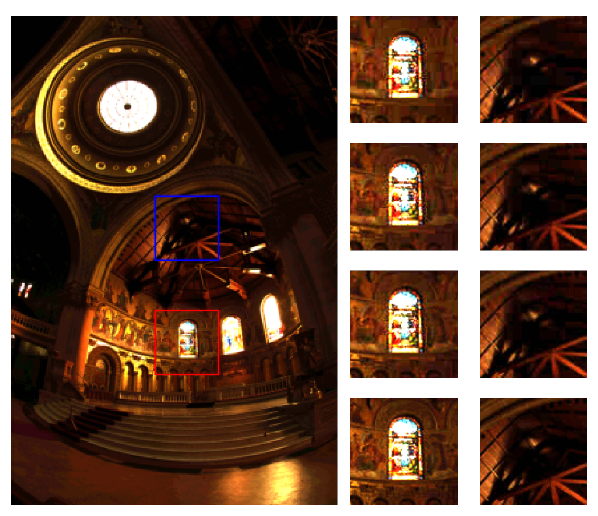
- For the red box which is the bright area, and the blue box which is the dark area, the subjective image quality of the proposed method is slightly better than JPEG XT profile A, B, C.
Reference
[2020 VCIP] [Han VCIP’20]
HDR Image Compression with Convolutional Autoencoder
Codec Intra Prediction
JPEG [MS-ROI] [Baig JVICU’17]
JPEG-HDR [Han VCIP’20]
HEVC [Xu VCIP’17] [Song VCIP’17] [Li VCIP’17] [Puri EUSIPCO’17] [IPCNN] [IPFCN] [HybridNN, Li ICIP’18] [Liu MMM’18] [CNNAC] [Li TCSVT’18] [Spatial RNN] [PS-RNN] [AP-CNN] [MIP] [Wang VCIP’19] [IntraNN] [CNNAC TCSVT’19] [CNN-CR] [CNNMC Yokoyama ICCE’20] [PNNS] [CNNCP] [Zhu TMM’20] [Zhong ELECGJ’21]
VVC [CNNIF & CNNMC] [Brand PCS’19] [Bonnineau ICASSP’20] [Santamaria ICMEW’20] [Zhu TMM’20]